The aim of this project was to design a multi-user database system for an online shoe store.
The first step was to identify the entities, relationships and attributes by analysing the project brief. The entities are the things of significance about which information needs to be known, such as shoes, customers and orders. Relationships explain how the entities are related (one to one, one to many), and the attributes contain specific information about the entities, such as shoe types, gender and payment method. The result of this is a conceptual entity relationship diagram, which is a first attempt at modelling the database.
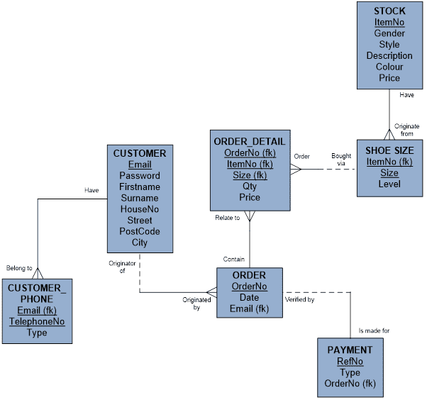
The next step is to break down any many to many relationships as these cannot be represented by a relational database. The conceptual diagram had a many to many relationship between ‘order’ and ‘stock’ i.e. each stock item may be bought via one or many order/s, and each order must be issued for one or many item/s of stock. A weak entity called ‘order detail’ was created to break this relationship down. Now each order must contain one or many order detail/s, and each order detail must relate to only one order (a one to many relationship). Each stock item may be bought via one or many order detail/s, and each order detail must order only one stock item (also a one to many relationship). This is depicted in the logical entity relationship diagram.

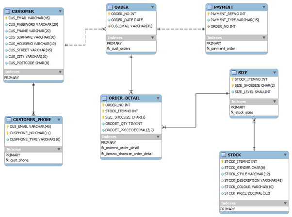
The normalisation process was next. This is required to minimise data redundancy which causes integrity problems and update/delete transactions may not be consistently applied to all copies of the data causing inconsistencies. Normalisation was carried out up to Third Normal Form (3NF). This helped identify three more entities that were previously missed. A data dictionary was then produced to identify all of the data types for the attributes. The model was now in a suitable state for it to be created in an actual DBMS. MySQL (later migrated to SQL Server) was chosen for this as it is a widely used and readily available DBMS. The physical entity relationship model depicts the MySQL database.

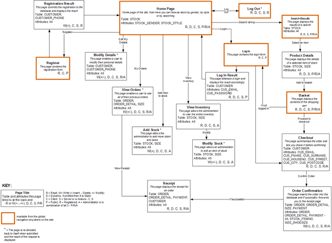
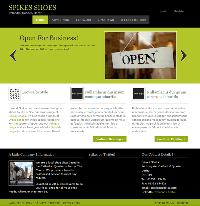
A front end was then created using PHP to test the database. To accomplish this a navigation map was produced by applying use case scenarios to the system to identify all of the pages that are required, which tables and attributes are required, whether the page is static or dynamic, public or private, and if the page requires read or write permissions on the database. The idea is that a front end developer can pick this up and have an immediate overview of how to put the site together. It is also often shown to business managers for approval.

A second version of the system was created using SQL Server and ASP.Net. This combination of open source and proprietary systems provided a broad appreciation of the available DBMS that exist in the industry and reinforced the strength of the design as it was easily portable to another set of technologies.
